External Trigger
The External Trigger feature fires a hardware GPIO pulse from a UWB sniffer when a user-defined sequence of packet events is observed on the air. It turns MantaTrace into a trigger source for external lab equipment — oscilloscopes, logic analyzers, protocol analyzers or a device under test — so you can line up an external measurement with a precise over-the-air event such as a BLE connection request or the start of a UWB ranging session.
You describe the sequence as a trigger chain: an ordered list of stages, each matching one kind of packet (BLE and/or UWB, on any running interface) with optional length, timing and repetition constraints. When the chain completes — or fails, depending on the outcome you choose — the app sends a trigger command to the selected UWB sniffer, which pulses its trigger GPIO pin.
Note: do not confuse External Trigger with the MantaTrace Time Sync feature. Time Sync works in the opposite direction: an external GPIO input on the sniffer resets the UWB timestamp counter so multiple boards share a common time base (shown as a violet "Time sync" banner in the packet list). External Trigger is a GPIO output fired by observed packets. See the Time Sync note at the end of this page.
Opening the trigger panel
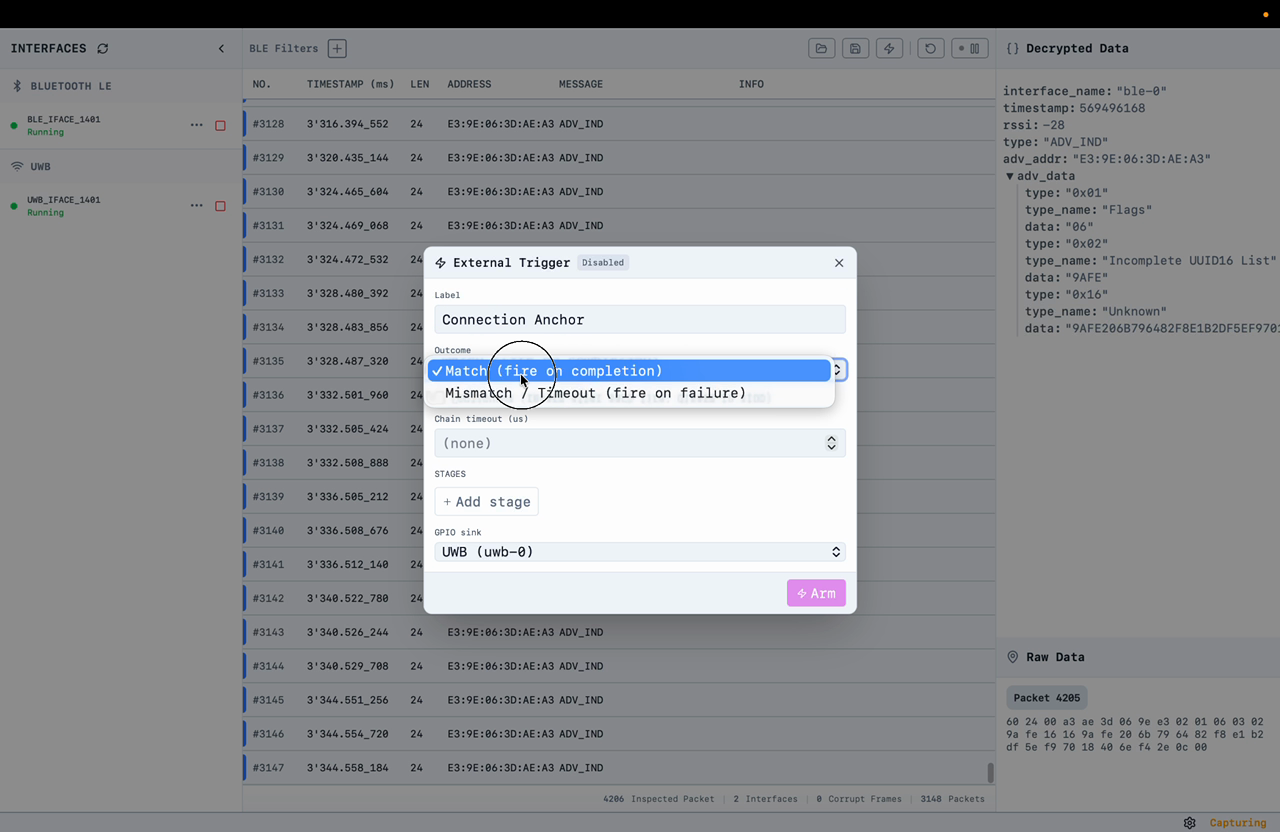
Click the lightning-bolt icon in the top toolbar to open the External Trigger panel. The badge next to the title shows the current state: Disabled, Armed or Fired.
Chain settings
Label – a free-text name for the chain. It appears in the inline markers in the packet list (e.g. "Connection Anchor").
Outcome – when the GPIO fires. Match (fire on completion) pulses the GPIO when every stage has been satisfied in order. Mismatch / Timeout (fire on failure) pulses the GPIO when a stage times out or the timing constraints are violated — useful for catching the absence of expected traffic.
Continuous – when ticked, the chain re-arms itself after each fire and keeps running until you disarm it. When unticked (default), the chain is one-shot: it fires once and disarms.
Chain timeout (us) – an optional whole-chain deadline in microseconds, in addition to any per-stage timeouts.
GPIO sink – the UWB interface whose trigger pin is pulsed when the chain fires. The pulse is always emitted by a UWB sniffer, even if the stages match BLE traffic.
Reset UWB timestamp – when enabled, the trigger output also resets the UWB sniffer's timestamp counter, exactly as a pulse on the Time Sync input would. The trigger output is already connected to the timestamp reset internally, so no external wiring is needed: subsequent UWB timestamps restart from zero at the trigger instant, marked by the violet Time sync banner in the packet list.
Stages
Add stages with + Add stage. Each stage waits for its packets in order — stage 2 only starts matching after stage 1 has passed.
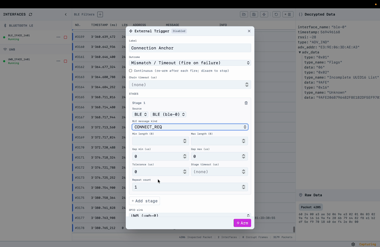 Each stage has the following fields:
Source – the interface kind (BLE or UWB) and the specific running interface to listen on.
BLE message kind (BLE sources) – the packet type to match: any advertisement, ADV_IND, ADV_DIRECT_IND, ADV_NONCONN_IND, ADV_SCAN_IND, ADV_EXT_IND, SCAN_REQ, SCAN_RSP, CONNECT_REQ, AUX_CONNECT_RSP, any data-channel packet, the firmware connect / disconnect events, or the CCC Digital Key anchor kinds — CONNECT_IND (procedure 0, connection event 0 anchor) and LL_PHY_UPDATE_IND (procedure 1, PHY-update event anchor).
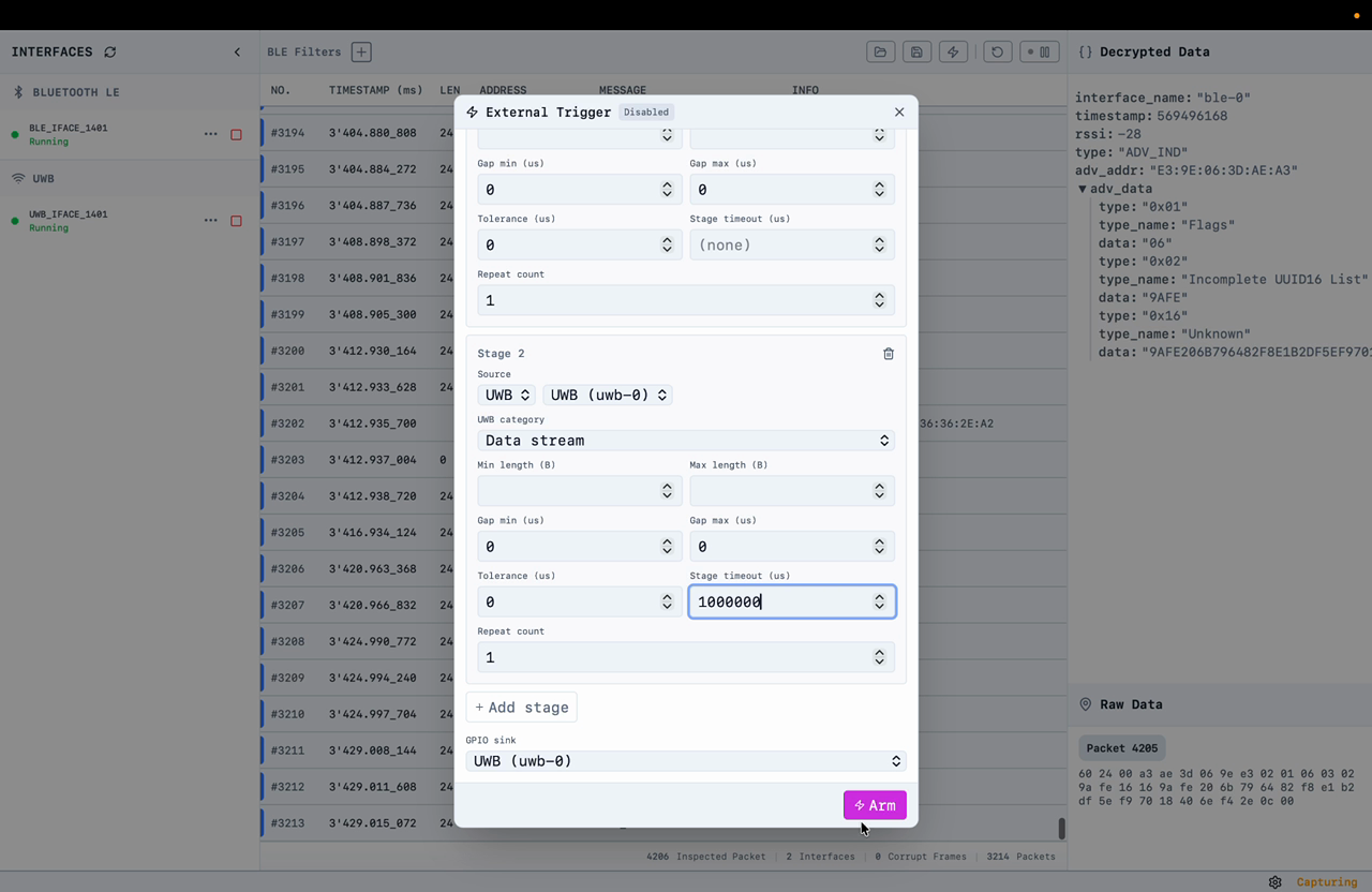
UWB category (UWB sources) – the UWB packet category to match, currently Data stream (ranging traffic).
Min / Max length (B) – optional inclusive bounds on the packet payload length in bytes. Leave blank to accept any length.
Gap min / Gap max (us) – the allowed time window, in microseconds, since the previous accepted packet. Leave at 0 to accept any gap.
Tolerance (us) – a symmetric allowance applied to the gap window.
Stage timeout (us) – optional deadline for this stage. If the stage is not satisfied within the timeout, the chain evaluates as Mismatch / Timeout.
Repeat count – how many matching packets are needed to pass the stage (default 1).
Arming and inline markers
Click Arm to start the chain. Trigger activity is recorded inline in the packet list, exactly where it happened in the stream:
A blue STAGE n PASSED banner each time a stage completes.
A red CHAIN FIRED banner when the chain fires, showing the outcome (Match or MismatchOrTimeout), the GPIO sink, and whether the chain disarmed (one-shot) or re-armed (continuous).
A CHAIN ENDED banner when a one-shot chain finishes or you disarm manually.
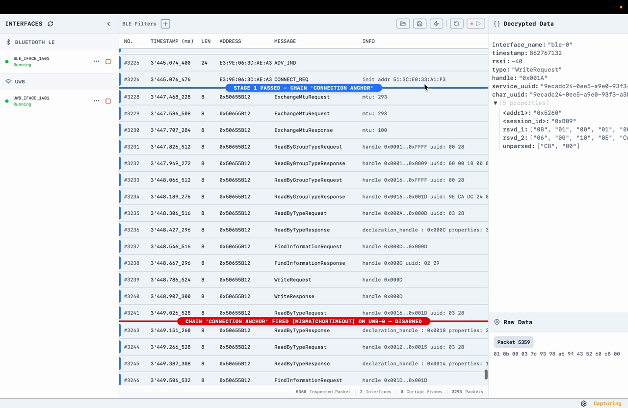 Marker rows are informational only — they consume a packet number but carry no payload, and they are not written to saved capture files.
Walkthrough: two-stage BLE + UWB chain
The recording below builds a representative two-stage chain: stage 1 matches a BLE CONNECT_REQ, stage 2 matches UWB ranging traffic with a 1-second stage timeout, and the GPIO pulse is emitted on the UWB sniffer. The CCC time-sync use case described in the next section follows the same pattern, with the anchor PDUs as the stage-1 match.
CCC Time Sync use case
In a CCC Digital Key (Car Connectivity Consortium) session, the vehicle and device first connect over BLE and then start UWB secure ranging. The CCC specification defines the UWB ranging timing relative to the BLE connection: the Time Sync message anchors the start of the UWB ranging block to a BLE connection event anchor point. Validating that relationship — did ranging start when the Time Sync message said it would? — means putting the UWB timestamps on the anchor timeline. The External Trigger, combined with Time Sync, does exactly that.
How it works
For this use case the trigger output drives the UWB sniffer's Time Sync timestamp reset — the two are already connected internally, so enabling the Reset UWB timestamp option is all that is needed for a trigger fired by BLE traffic to reset the UWB clock:
The trigger stage matches the anchor-relevant PDU directly: CONNECT_IND for procedure 0 (the anchor of connection event 0) or LL_PHY_UPDATE_IND for procedure 1 (the anchor of the connection event carrying the PHY update).
When the relevant PDU is received, the BLE sniffer arms the trigger in hardware — not to be confused with arming the chain in the UI or CLI.
The GPIO edge is then generated by the radio's RF GPIO hardware at packet reception, which has a direct correlation with the connection event anchor point. No CPU scheduling or host round trip is in the timing path.
- The edge resets the UWB sniffer's clock through the Time Sync input. The received PDU containing the anchor is then qualified, and software applies the UWB clock delta.
The result in the UI: UWB timestamps accurate to better than 100 ns relative to the CCC anchor point.
The stage timeout doubles as the failure detector: if the expected UWB traffic does not arrive in time, the chain reports a timeout — so failing runs are captured as clearly as passing ones.
Walkthrough
1.Set up the BLE trigger stage – Source BLE; message kind CONNECT_IND (procedure 0) or LL_PHY_UPDATE_IND (procedure 1). Enable Reset UWB timestamp — the trigger output is connected to the UWB timestamp reset internally, so no external wiring is needed.
2.Add a UWB stage with a missed-packet timeout – Source UWB, category Data stream; set the stage timeout to the longest acceptable delay from the BLE anchor to the first ranging frame.
3.Successful run – the UWB frame arrives within the timeout. Its timestamp — and every UWB timestamp from the sync onward — is shown relative to the anchor point.
4.Failing run – the UWB frame arrives too late: the UI (and CLI) indicate the trigger timeout. If and when UWB packets do arrive, their timestamps are still relative to the anchor, so the lateness can be read directly from the packet list and the UWB Timeline Grid.
The same chain runs headless: the trigger setup is passed to the command line tool as a JSON file, and trigger firings and timeouts are reported over the CLI exactly as the UI banners show them.
GPIO output hardware
The trigger pulse is generated by the UWB sniffer firmware. Default trigger pins:
- nRF DK: P1.01
- Murata Type2AB EVM: P1.12
- Murata Type2BP EVK: PIO0_3 (red LED2, active-low)
- USB dongle: P0.13
The default pulse is 100 ms wide, so a firing is visible on a board LED, and active-high (active-low on the Type2BP, to match its LED). Pin, polarity and pulse width are device configuration (not per-chain) and can be overridden per device in the sniffer's config.json; when no override is set, the firmware defaults above apply.
Not the same feature: MantaTrace Time Sync
MantaTrace also supports a hardware Time Sync input: a pulse on the sniffer's timestamp-reset GPIO input zeroes the UWB timestamp counter, letting several sniffer boards be aligned to a shared external clock edge. When this happens a violet "Time sync — timestamp counter reset" banner appears in the packet list and subsequent timestamps restart from zero.
The two features are independent and complementary: External Trigger produces a GPIO output when packets are seen; Time Sync consumes a GPIO input to align timestamps. In a full CCC measurement setup they can be combined — reset the sniffers' clocks from a common reference, then use an External Trigger chain to mark the BLE-to-UWB handover.
