Table of Contents
Time Sync
MantaTrace aligns packets from every running interface onto one shared timeline, and — with supported firmware and a little wiring — can align the hardware clocks of multiple UWB sniffer boards to a common zero. This page covers both. Note: Time Sync is not the same feature as the External Trigger. Time Sync consumes a GPIO input to reset the sniffer's timestamp counter; the External Trigger produces a GPIO output when a packet sequence is observed. The two are independent and can be combined.Software timestamp alignment
Every sniffer board reports timestamps from its own free-running device clock, in its own tick units. The app unwraps these counters (they roll over regularly) and converts them to a session-relative nanosecond timeline, so UWB, BLE and wM-Bus packets can be compared on the same axis. This alignment is what powers the timestamp column in the Packet Preview List, including the optional Delta (ms) mode (enabled in Settings), which shows the time since the previous packet on the same interface.Hardware sync between boards (TRP)
A pulse on the sniffer's timestamp-reset input zeroes the UWB timestamp counter. When this happens, the app re-anchors that interface's timeline to exactly zero and inserts a violet Time sync — timestamp counter reset banner row into the packet list at the point of the reset. Feeding the same pulse to several boards gives them a common time base, so timestamps from different sniffers line up and cross-board deltas become meaningful.Wiring recipe (nRF DK boards)
When two or more UWB sniffers are capturing at once, the app shows a one-time Sync sniffer time bases reminder with this recipe (a "Don't remind me again" checkbox hides it permanently):1.Fit the sync jumper on every board – connect J17-4 (DW_GPIO7) to J17-6 (P1.11) with a jumper on each board, so the sync pulse reaches the UWB chip's SYNC input.
2.Wire the boards together – connect the sync line P0.30 to P0.30 and GND to GND across all boards.
3.Start the sniffers, then press the sync button on one board – all connected boards reset their counters together. On long captures, press it again if the clocks drift apart.
The signal chain is: button (P0.30) → firmware pulses P1.11 → jumper → DW_GPIO7 (UWB chip SYNC input) → one-shot time-base reset that zeros the counter.
After the button press you should see the violet Time sync banner appear on each synced interface, and subsequent timestamps restart from zero.
CCC Digital Key anchor time sync
For CCC Digital Key measurements, Time Sync goes beyond a button press: a MantaTrace BLE sniffer drives the sync line itself, referenced to the exact timing anchor the CCC specification uses. The External Trigger output is already connected internally to the timestamp reset described above — enable the trigger's Reset UWB timestamp option and a trigger fired by BLE traffic resets the UWB clock, with no external wiring.What it does
In a CCC Digital Key session, the vehicle and device connect over BLE and then schedule UWB secure ranging relative to a BLE connection event anchor point (CCC-TS-101 Digital Key v4.1.0 §19.4.4). The BLE sniffer passively watches that connection and produces a hardware GPIO edge correlated with the anchor point. Fed into the UWB sniffer's timestamp-reset input, that edge zeroes the UWB counters — so UWB packet timestamps land on a timeline referenced to the BLE connection-anchor epoch, exactly the reference the CCC Time Sync message uses. The BLE sniffer is a passive observer: it never transmits, and it never sends the CCC Time Sync message itself — that is the device's job. It simply observes the same anchor point the device is required to observe, and exports it on its GPIO. An anchor point is the start of a connection event's first packet — for a passive sniffer, the reception of the central's transmission.The two procedures
CCC defines two time-sync reference points (CCC-TS-101 v4.1.0 §19.4.4), matched by two trigger message kinds:How the edge relates to the anchor
When the relevant PDU is received, the BLE sniffer arms the trigger in hardware (not to be confused with arming the trigger chain in the UI or CLI). The GPIO edge is then generated by the radio's RF GPIO hardware at packet reception — a modem hardware signal with no CPU scheduling or host round trip in the timing path. The edge is not coincident with the anchor, and does not need to be. The anchor point is the on-air start of the event's first packet, while the modem signal asserts when the demodulator locks onto the access address — preamble + access address + demodulation delay later (on the 1M PHY, roughly 40 us). That delay is a fixed, PHY-dependent constant, so the edge correlates directly with the anchor: software simply subtracts the known offset. The edge resets the UWB sniffer's clock through the Time Sync input. The received PDU containing the anchor is then qualified, and software applies the UWB clock delta. The result: the UI shows UWB timestamps accurate to better than 100 ns relative to the CCC anchor point.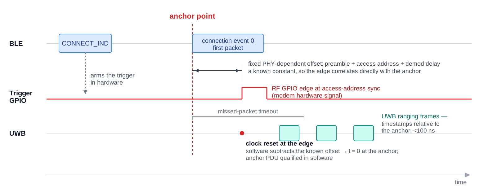 Procedure 0 shown:
